

NOTE: If you are a single-monitor user, this is overkill. See Easy LightBoost HOWTO.
Blur Busters has long been very enthusiastic about NVIDIA LightBoost for motion blur elimination, with the hugely popular LightBoost HOWTO running on 120Hz monitors. However, for people who spent thousands of dollars on a surround setup, read on:
Driver Disaster For Triple Surround LightBoost
 Surround LightBoost 2D users got a very unpleasant surprise from NVIDIA during Fall 2013. People who upgraded to NVIDIA GeForce Drivers 327.23 and later, lost ability to use LightBoost for 3 monitor surround. Interestingly, AMD Eyefinity users are unaffected; these users easily use LightBoost with ToastyX Strobelight Utility. Ironically, LightBoost easier to use on AMD than NVIDIA? NOTE: single monitor users are unaffected for both NVIDIA and AMD.
Solution: Hardware EDID Modification
To satisfy upset users sitting on 4-figure investments in NVIDIA products, Blur Busters is pleased to provide a solution, thanks to Toni Wilen, the author of WinUAE (Amiga emulator) who is a triple surround LightBoost user.
These advanced instructions involve opening up your monitor for a minor modification. This is to physically disconnect a write-protection pin for the EDID chip, and then using a utility to reflash the EDID with LightBoost-specific modes (modes containing a larger Vertical Total).
You will also need a separate computer running an older graphics card, for the EDID reprogramming part, since a lot of EDID utility software (e.g. PowerStrip for Windows, edid-rw for Linux) only work with older graphics cards.
After this process is done, LightBoost will be enabled by default, even at the POST screen at bootup! This process should not interfere with the upcoming G-SYNC upgrade, though you may need to re-flash the EDID back to original. Proceed at your own risk.
Step-by-Step Instructions for ASUS VG248QE
These instructions assume you have the ASUS VG248QE computer monitor, one of the most popular LightBoost-compatible monitors. Other monitors (e.g. BENQ XL2411T) have very close similarities, however, these instructions are only tested on the VG248QE.
1. Get organized. You will need a Philips screwdriver. A soldering iron is highly recommended, however, an ultra-sharp large utility knife blade (fresh, new ‘exacto’ type blade) will also work if you are extremely careful (an accidental slip will do a lot of damage).
Make sure your work area is washed/cleaned, as you don’t want dirt getting into your monitor innards. You will be temporarily removing screws, so do not lose them! Get a few sandwich bags, small containers, or several cups, to store loose parts in.
2. Make sure you don’t have static electricity. Touch a grounded metal object (e.g., the metal surface at the back of your computer). Also, make sure your monitor has been unplugged for at least 15 minutes, so there’s no charge left in your monitor’s capacitors.
3. Remove the plastic casing from the monitor. This is called “de-bezelling” your monitor, which surround monitor users often do in order to reduce the gap between monitors during surround mode. This video, by HatlessChimp from overclock.net, provides good instructions on how to disassemble the ASUS VG248QE:
https://www.youtube.com/watch?v=GeDNb2Vebfk
If you are only doing this temporarily, simply stop following the video once you gain access to the interior (5min into video).
4. Lay the the screen face down carefully, with the metal rear of the monitor facing upwards. Make sure your surface is clean and completely clear of debris, so it does not scratch or damage the glass of your monitor.
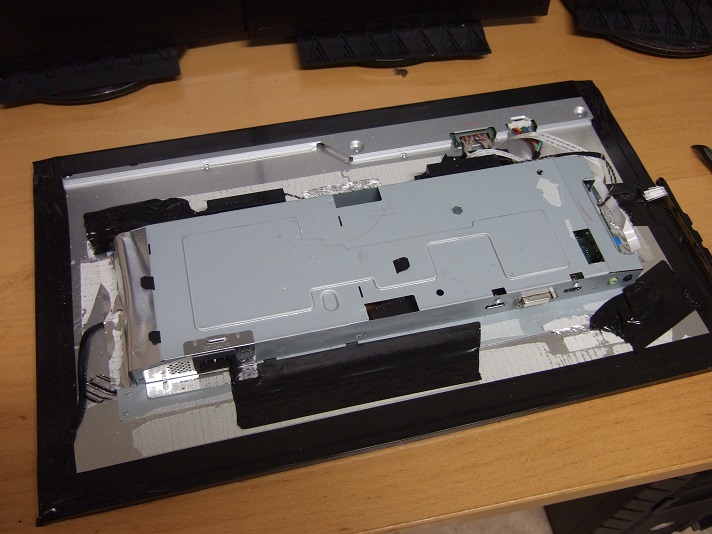
5. Remove the metal cover. Do this by carefully removing all tape pieces surrounding the large protruding metal cover (tape may be silver color instead of black). Then unscrew all 4 screws near video connectors. And then disconnect the speaker cable. Once done, you can carefully lift the metal cover, revealing the green circuit board underneath:
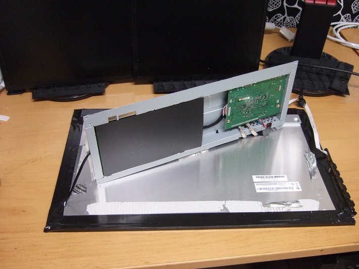
6. Unscrew the circuit board. Remove the two screws that hold the main circuit board. Upon doing this, you can now see the chips sitting on your monitor circuit board.
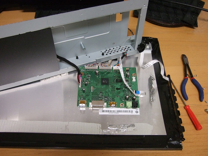
7. Find the correct EDID chip for DVI. See attached image, with circle. The correct chip you want is immediately behind the DVI connector. It is a tiny 8-legged chip, and says “ATML” on it as the first few letters. For the electronics geeks, this is the DVI I2C EEPROM chip, an Atmel 24C02C. There are two of them, one for HDMI, and one for DVI. However, we only need to modify the one for DVI.
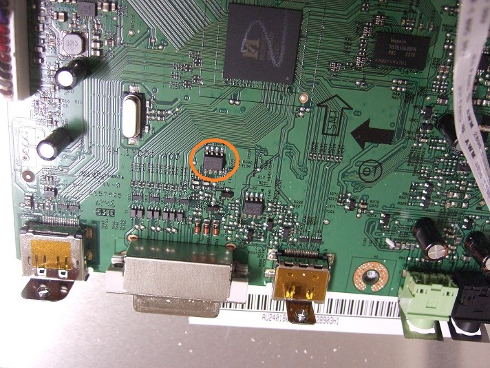
8. Disconnect the Write Protect Pin of the chip. This is pin #7 of the Atmel chip. If you have the DVI port facing towards you, this leg is third from left. Tip for Electronics newbies: Pin numbers are often counted counterclockwise from pin #1 indicated by a white dot on the chip. If you have the same chip as in the screenshot, the correct pin will be on the opposite edge as the white dot, and be right above the label “ATML”
![]()
Soldering Iron Method: The use of a electronics soldering iron, with a thin tip, is recommended. Heat the pin just enough until the solder melts, and bend the pin upwards using the soldering iron’s tip (or another pointy metal tool). Do not overheat.
Utility/Exacto Knife Method: This method is accident prone, and easily does accidental damage. However, it works if you are careful with the knife method. Use a fresh, new utility kife blade. Carefully and slowly, with light pressure, cut pin #7, by sawing through it gently until it cuts through. Gentle cutting is less accident prone than a hard push (where a sudden slip accident can sever multiple circuits). Use a very sharp, fresh blade, so it is easy to cut the pin with just light pressure, minimizing the chance of a “slip” accident.
Note for Electronics Geeks: The ATMEL 24C02C datasheet says the pin should ideally be connected to ground, however, leaving the pin unconnected works too.
9. You’re Done. Reassemble the monitor. Reattach the circuit board (2 screws), reattach the metal cover (4 screws and tape, use new tape if necessary), and reassemble casing if desired (or keep it de-bezelled, during surround use).
Reprogramming the EDID chip of ASUS VG248QE
Download either one of these files:
(a) edid_120hz-lightboost-only.bin — If you only want 120Hz modes
(b) edid_120hz-lightboost-plus-60hz.bin — If you also want 60Hz modes.
Choose a method of flashing the EDID:
Most approaches require the use of an older graphics card (e.g. Geforce GT 8800) since several free EDID reprogramming utilities often don’t work from newer graphics cards. When you reprogram your EDID, make sure you connect only one monitor at a time, and reprogram them one at a time. Repeat these steps for each monitor.
Option #1: Paid method, Windows 32-bit, Old Graphics Card
The paid version of PowerStrip (free version won’t work for this) is capable of reprogramming the EDID of your monitor using these .bin files from a Geforce GT 8800 (and certain older cards) under a 32-bit Windows system. This is easiest done on a separate computer, so pull out an old 32-bit Windows box (even running Windows XP) and an older Geforce or AMD/ATI card, preferably a GeForce 8800 GT as it has been tested and known to work. You can borrow somebody else’s older computer for this, too.
Install PowerStrip, reboot, run, select system tray icon -> Options -> Monitor Information.
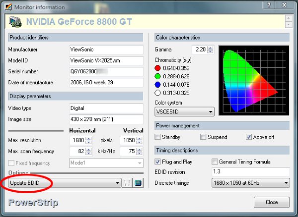
Credit: Screenshot from Komiel’s blog
First, backup your monitor’s EDID, and save to a file. This allows you to undo the permanent LightBoost EDID later, if necessary. This is useful when you want to sell your monitor, for example. The EDID also contains your monitor’s serial number, which you will be overwriting! If PowerStrip cannot find your EDID, try a different graphics card. For example, a GeForce 8800 GT worked, while GeForce 8600 GT did not find an EDID.
When you select “Update EDID”, you may see “EEPROM Error“, saying “An EDID EEPROM was not detected on the selected monitor. Do you want to scan the bus for other EDID EEPROMs?“. When you click Yes, you may see another pop-up message “EEPROM Found: <MONITOR>” and a message “An EDID EEPROM has been found at port #1. Do you want to attempt writing to this EEPROM?“. Click Yes. Select the .bin file and PowerStrip will flash your monitor with the new EDID. Once you’re done, go to Testing your New LightBoost.
Option #2: Free method, Linux shell, Old Graphics Card
This method is good if you are reasonably familiar with Linux. You might still need to run on an older graphics card for this to work (GeForce 8800 works) depending on support. Obtain your favourite Linux distribution (e.g. Linux packages, or bootable LiveCD .iso). Next, obtain a copy of edid-rw from Sourceforge, or install using sudo:
sudo apt-get install python-smbus edid-decodeOnce you’ve got the ‘edid-rw‘ and ‘edid-decode‘ commands installed, find your I2C bus number by replacing X with 0, 1, 2 until you see valid EDID output:
./edid-rw X | edid-decode
Once you’ve found the number for value X, use the number value for all subsequent mentions of X in commands. Next, backup monitor’s original EDID. Remember that each monitor has different EDID serial numbers, so keep separate EDID backup files from each monitor. Backup your original EDID using this command (replacing X with number):
./edid-rw X > name_of_backup_file.binChoose one of the .bin files (e.g. edid_120hz-lightboost-only.bin) and make sure it is in the same folder as edid-rw. Next, reprogram your EDID with the following command (replacing X with number):
./edit-rw -w -s 0.01 X < edid_120hz-lightboost-only.binNote: The small delay (-s 0.01) is necessary, otherwise you get error messages. If you are trying to reflash other monitors, you may need larger values (especially on older models, such as the ASUS VG278H which has very slow I2C). Also, if you ever want to restore your old EDID, this is the same command you use (with the backup .bin file you saved). This is useful when you want to sell your monitor, for example.
Now, verify your EDID with this command (replacing X with number):
./edit-rw X | edid-decode
If all checks out, you’re finished with this monitor. Repeat all the above steps with the next monitor of your surround setup, until you are finished with each monitor. Once you’re done, go to Testing your New LightBoost.
Alternate Options
If you prefer to use a different EDID flashing utility, you are on your own. Be careful! The use of Tomasz Orczyk’s EDID converter [WARNING: Untested] can allow you to convert .bin files to other formats (.dat or .raw) compatible with other EDID utilities. If you discover an easier method of flashing your EDID, please post in the comments!
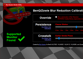
Testing Your New Permanent LightBoost
Once done, reconnect all your monitor(s) to your original system, power them up. Install and run ToastyX Strobelight once. This is a one-time procedure to wake up LightBoost permanently, after having unplugged your monitor. Once this is done, you don’t need to run Strobelight again even after reboots (Unless you want to use Strobelight for easy adjustments, including LightBoost brightness). In fact, next time you reboot, your monitor will have LightBoost enabled during the BIOS / UEFI screen, or even when rebooting into a different operating system that automatically configures from the hardware EDID!
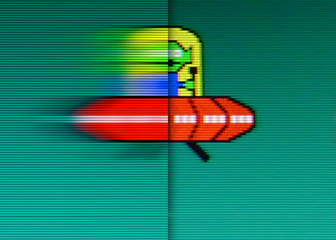
Next, set up your surround mode (e.g. triple monitor portrait surround), and LightBoost will continue merrily working, independently of your graphics drivers, assuming the EDID was flashed correctly into your monitor.
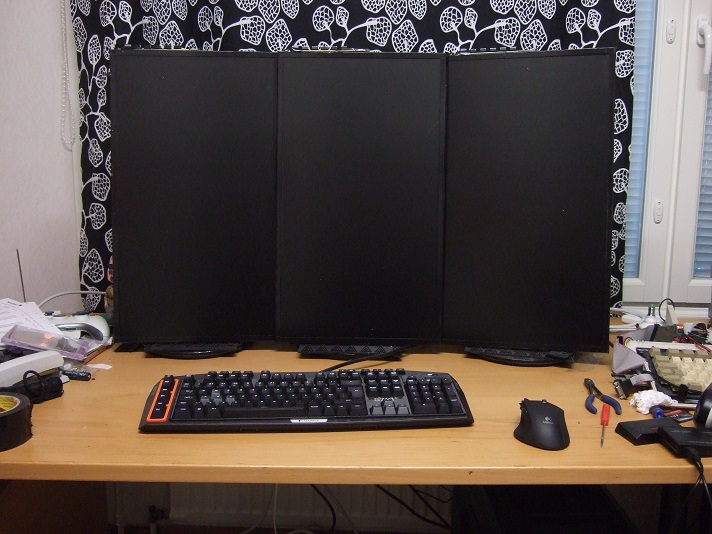
Triple LightBoost portrait surround working with latest GeForce drivers.
Remember if you unplug your monitors from power, you will need to re-run ToastyX Strobelight (or 3D Vision initialization) once, to wake up LightBoost, and make it stay stuck on again.
Interaction With Software EDID Overrides
The use of the hardware EDID method does not prevent the ability of doing software-based EDID overrides using ToastyX Custom Resolution Utility (CRU). For example, even if you installed the 120Hz-only EDID, you can still add 60Hz modes manually via CRU. However, these modes will not work in surround modes. Only the hardware-installed EDID (flashed on the monitor) will reliably work in triple surround mode with the newer NVIDIA drivers.
Future G-SYNC Upgrade
This modification should not interfere with G-SYNC, as G-SYNC uses the DisplayPort connection rather than the DVI connection. However, just in case, you should keep a backup of your original EDID, so you can reflash your monitor’s EDID back to original. Also, the G-SYNC upgrade also includes a LightBoost sequel that was revealed earlier.
Credits
These instructions were brought to you as a Blur Busters exclusive, provided by reader Toni Wilen, the author of the WinUAE Amiga Emulator (www.winuae.net). If you have improvements (e.g. easier Windows EDID programming utilities) or a way to bypass the need to open up the display, please contact [email protected].
Feel free to donate to Toni if he is a hero for saving your 4-figure-priced setup. If you love emulators, we’d like to note that Toni’s WinUAE has software-based black frame insertion! This permits 60Hz with reduced motion blur on 120Hz monitors.
If you are looking for a new monitor, see the Official List of 120Hz Monitors.