

Originally Written in 2013 – This Used To Be www.scanningbacklight.com
Advanced article written by Blur Busters Founder Mark D. Rejhon for electronics engineer and display engineer geeks: Those who know soldering irons and oscilloscopes. It may also help display manufacturers that have never worked with motion-blur-eliminating strobe backlights before.
Index
- Introduction: Eliminating Motion Blur With Strobing
- The Problem With Scanning Backlights
- Strobed Backlights is the Solution
- Some Engineering Gotchas with Strobe Backlights
- Easy Electronics Mods of Existing LightBoost Monitors
- Understanding LCD Refresh Behavior Via High Speed Video
- Hacking Existing Monitors: Strobe Backlight Mod
- Testing A Strobe Backlight
- Photographing Motion Blur: Stationary Camera vs Pursuit Camera
- Advanced Strobe-Optimized LCD Overdrive Algorithms
- Advanced Input Lag Considerations
- Advanced Multipass Refresh Algorithms
- Flicker/Eye Comfort Considerations
- Reducing Research & Development Costs For Manufacturers
- Alternative Display Technologies (OLED, etc)
- Strobing on Variable Refresh Rate Displays
- Linear Motion Blur Versus Gaussian Motion Blur
- LightBoost Hacking References
Introduction: Eliminating Motion Blur With Strobing
Before the LightBoost strobe backlight was discovered to be an easy way to eliminate LCD motion blur, Mark Rejhon (aka Chief Blur Buster) worked on home-brew Arduino scanning backlight experiments. In fact, Blur Busters started because of a tweet reply from John Carmack agreeing with my Arduino scanning backlight. Blur Busters’ former domain name was www.scanningbacklight.com which now redirects to this site.
The LightBoost buzz on the Internet got coverage by several websites (AnandTech, ArsTechnica, TFTCentral, etc). Most of these media articles cite Blur Busters as the Internet’s #1 source of LightBoost motion blur elimination information. A few manufacturers are now experimenting with strobe backlights, indirectly because of the LightBoost buzz on the Internet, which Blur Busters help create. Other displays also use strobe backlights, such as NIVIDA’s ULMB, BenQ’s DyAc, or Sony’s low-lag Motionflow Impulse used in Game Mode.
Recently, Michael Abrash of Valve Software talked about the need to reduce persistence in displays for virtual reality usage. One of the techniques discussed, was the use of strobing to reduce persistence. This page tells hobbyists, electronics tinkerers, and small manufacturers how to get started in creating strobe backlights, and experimenting with them.
Also see Advanced Strobe Crosstalk FAQ.
The Problem With Scanning Backlights
First, see the Scanning Backlight FAQ that I (Mark Rejhon) created. This covers information about scanning backlights. Several issues have been found with scanning backlights, from the perspective of a homebrew modification:
(1) Backlights are way more inefficient than edgelights. With 250 watts of LED’s, it only gets about double the brightness of a 25 watt edgelight already built into a typical modern panel. For a backlight, one needs good diffusing optics and/or over one-thousand parabolas Possible homebrew fixes: Strips of horizontal mirrors or linear parabolas made out of curved thin reflective strips. Also, it may be feasible to use a 3D printer to print parabolic reflectors for LED ribbons (and then using metallic paint or electroplating).
(2) Scanning backlights are WAY more inefficient in eliminating motion blur than strobe backlights. TFTCentral also covered this in their Motion Blur Reduction Backlights article. Scanning backlights have the advantage of lower input lag and less complicated LCD response-time acceleration, and would more successfully work with IPS panels. Unfortunately, there’s an amazing amount of light leakage between off-segments and on-segments of LED backlights, as you attempt to sequentially light-up rows of LED’s. If you keep the LED’s close to the LCD panel, you can get about 20:1 contrast between the off-segments and on-segments.
Unfortunately, if you don’t use parabolic mirrors, then putting the LED’s too close to the panel, you get a beady effect even with a good diffuser:

To solve this problem is technically challenging for homebrew:
(A) Proper diffuser, parabolas, mirrors.
(B) Adding diffusers help a lot, but they kill a lot of light.
(C) The further you move back the LED’s, diffusing becomes easier but you lose contrast ratio between ON segments and the OFF segments; the more leakage between segments.
Even local dimming found in high-end LCD televisions (contrast enhancement via turning off individual backlight LED’s behind the LCD panel), often only succeed in getting approximately about ~10:1 or 20:1 real-world contrast ratio amplification. For example, turning a 1:2000 panel into a 1:20,000 panel, for ANSI checkerboard contrast (a screen that simultaneously shows blacks and whites) because of this backlight diffusion. Likewise, the flashes between between adjacent scanning backlight segments severely reduces the achievable motion blur reduction you can get with a scanning backlight.
Some companies such as VPixx specialize in solving this problem. They have the VIEWPixx Scientific Research 120Hz Monitor with a scanning backlight with little backlight diffusion (measurements). However, this is far beyond the abilities of nearly all homebrew modders.
Strobed Backlights is the Solution
The solution is strobed backlights / edgelights — that flash all at once. This is what LightBoost does, as seen in the below popular high-speed video (which is also proof that it is now possible ot have LCD’s with CRT motion quality):
With all-at-once strobing, you can even use a simpler and more efficient edgelight.
With strobe backlights, you have no limiting factors in motion clarity:
(1) Not limited by LCD pixel transition speed anymore, as long as pixel transition speed is far less than one refresh cycle long.
(2) Not limited by backlight diffusion (A problem with scanning backlights)
And other advantages:
(3) It’s easy to do with an edgelight
(4) It’s far more efficient, less power.
With strobed backlights, you don’t have backlight diffusion during scanning backlights. Strobed backlights allows unbounded improvement to LCD’s. Once pixel transitions completely fit within the “OFF” period, there’s no upper limit to motion clarity of LCD — motion is as clear as how briefly you flash the backlight. It is actually theoretically possible to get far better motion resolution with LCD than with CRT if you’re able to successfully flash a ultrabright edgelight for an ultrashort time period, shorter than a typical CRT phosphor decay time (illuminate-and-decay cycle).
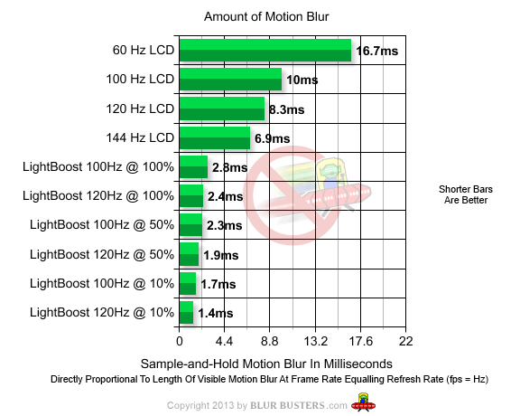
Strobe backlights have extremely high efficiencies in achieving true Motion Picture Response Time measurements (MPRT). In general, a full-strobe backlight is usually able to achieve MPRT’s exactly equalling the backlight strobe length:
With certain LCD panels fast enough to allow you to hide the vast majority of pixel transitions (Over 99%+) during the off-cycle between strobe backlight flashes, there is no upper limit to the motion resolution of an LCD. The motion clarity of an LCD is only limited by how briefly you are able to flash the strobe backlight. Modern LED backlights are able to be flashed very fast. Even the LED phosphor decay of white LED’s are typically less than 0.1 millisecond, so even the LED phosphor decay will not create human-detectable motion blur. In fact, you can bypass phosphor completely using RGB LED’s, and achieve an MPRT of less than a microsecond on an LCD via the strobe backlight technique (This is likely far shorter than necessary for maximum motion clarity to human eyes. Millisecond-scale and sub-millisecond-scale strobe lengths are more pratical, resembling short-persistence CRT phosphor).
Some Engineering Gotchas with Strobe Backlights
Unfortunately, going to a strobed approach results in several disadvantages:
(1) You need far faster LCD’s than if you were using scanning backlights. You need to fit pixel transition speeds to far less than 1 refresh long, so that you can finish your pixel transitions in total darkness for the entire screen at once.
(2) You need a very long vertical blanking interval to wait for pixel transitions of the refresh to settle.
……..Either in the original signal, killing your bandwidth;
……..OR artifically lengthened interval via partial display buffering and then accelerated scanout refresh — like LightBoost does).
(3) Even so, you can have asymmetry at the top edge of the display versus the bottom edge of the display, because the pixel transitions are fresher at the bottom edge of the display. This can manifest itself as increased ghosting at the top/bottom edge, depending on how the strobe backlight is timed.
Examination and disassembly of a LightBoost strobe backlight by an european researcher has revealed a large number of very interesting findings about how LightBoost works to solve the problems of strobe backlights. Some surprising discoveries were made, including partial buffering to create a longer blanking interval, phasing the strobe timing to slightly overlap next refresh, custom strobe-optimized overdrive algorithm that accounts for Y-axis of pixel for freshness prior to strobe, etc.
Easy Electronics Modifications of Existing LightBoost Monitors
It is even possible to modify existing LightBoost monitors (so we can take advantage of the LCD’s existing response-time acceleration). LightBoost hacking is *much* easier, and has been done by a few people to brighten and improve LightBoost backlights, by changing a few resistors. It’s also possible to shorten the LightBoost strobes, so that the backlight flashes for a shorter time period.
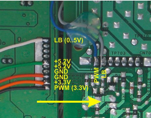
An European researcher, Marc Repnow, reverse-engineered LightBoost strobe control electronics (for scientific use) and found some key electrical contacts which make it possible to brighten/shorten the LightBoost pulses to reduce motion blur even further (better than LightBoost=10%).
bmg on HardForum made a successful modification to create a brighter LightBoost:
I finally got around to opening up my VG248QE. I hadn’t popped open an LCD before, so I was a bit nervous, but it went fine. The driver/power supply board is slightly different than the XL2411T, but very very close. The resistors that are switched in for Lightboost are identical values. The color coding and function of the connections between the controller and driver/power supply boards are identical also.
Since I wasn’t happy with the crappy black level in Lightboost mode, I considered increasing Lightboost resistor values, but decided it was overkill, so what I ended up doing was simply cutting the green and grey wires in the cable (the LB100-120hz current boost and LB120hz only additional boost). I soldered the grey wire ( for 33k LB resistor) on the driver to the green controller wire. That gives a modest current boost any time lightboost is enabled. The output will be slightly higher at 100hz if I ever use that refresh rate, but if so I’ll just drop down one step on the LB setting to match outputs. I connected the driver’s connector pin for the green (for the 11k LB resistor) wire to ground, to ensure it was disabled (unnecessary really). In my gaming/tv room that has subdued lighting, I’m currently at .12cd/m^2 minimum LCD output, and 89cd/m^2 max, that’s with LB20 and Contrast 90. That’s a contrast ratio of 740, which isn’t bad at all. I’ve got plenty of room to increase the output if needed, but I like around 90cd/m^2. The best black level I could get before the mod was .17cd/m^2 (LB10), which wasn’t all that “black”. I think the LB black on my monitor might have been worse than what’s normal. I made a custom LUT for CPKeeper, and the monitor really looks nice now.
Understanding LCD Refresh Behavior Via High Speed Video
It is important to gain an understanding of how LCD panels refreshes. High speed video is an excellent tool in gaining a better understanding of how modern LCD panels refreshes.
- See Why Do Some OLED’s Have Motion Blur?
This explains the sample-and-hold effect that creates motion blur. - See high speed video of CRT versus LCD.
Observe the sample-and-hold effect that occurs on LCD. - See high speed video of older 2007 LCD.
Example of LCD refreshes not compatible with strobe backlight. - See high speed video of newer 2012 LCD.
Example of LCD refeshes compatible with strobe backlight.
The refresh pattern of an older 2007 LCD looks like the following:
You will observe that there are some sequences in this video where three different LCD refreshes very obviously overlap each other. Such older LCD’s are unsuitable for strobe backlight conversion, since such LCD’s are in a perpetual state of ghosting with no clear moments to strobe a backlight through. Such older LCD’s should be avoided for strobe backlight conversion projects.
Frame grab from high speed video, of an LCD unsuitable for strobe backlight.
A high speed camera is not absolutely required, but it will be very helpful in determining how long a blanking interval you need between refreshes, in order to completely hide pixel transitions. A 480fps+ camera is ideal (e.g. Casio Exilim EX-ZR200, EX-FC200S, EX-F1, Fuji HS10, Nikon 1 J1); a 240fps camera is better than nothing (e.g. GoPro Hero 3). Some 1000fps capable cameras can be found for as little as $200! Be warned that some high speed mode is ultra-low resolution (approximately VGA resolution or less), but that is sufficient for panel suitability testing / strobe backlight testing.
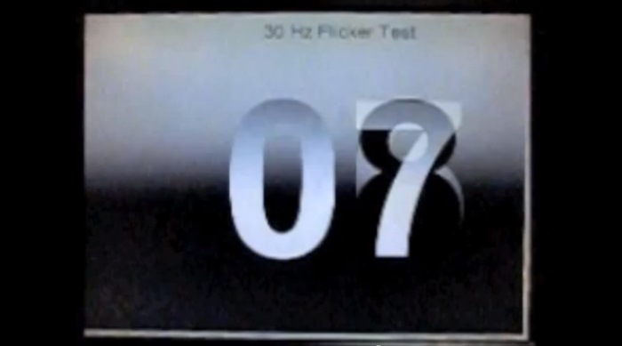
If you do get a high speed camera, a good test pattern for high speed camera use, is Blur Busters Motion Test (Flicker) which can help you determine how they refresh, and to help you with timing the strobe backlight flashes.
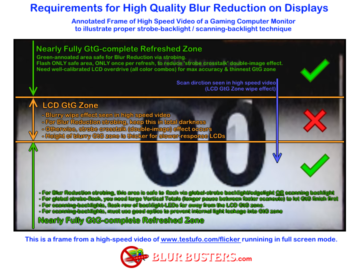
Finally, this annotated diagram helps people understand higher-quality strobe backlights:
Hacking Existing Monitors: Strobe Backlight Mod
This is the modification of an existing computer monitor to add a strobe backlight (LightBoost style) for anyone with electronics knowledge, ability to use oscilloscope, ability to build a simple pulsed power supply. This is the, far by the easiest homebrew hack to create a home-made LightBoost-like strobe backlight. A disadvantage of 60Hz is more flicker than LightBoost. An advantage of 60Hz is more safety margin for LCD pixel transitions, and less GPU is required for 60fps @ 60Hz.
- Get a cheap recent TN LCD with an extremely bright edgelight/backlight, preferably a panel with a good overclocking margin, preferably greater than 300cd/m2. It won’t be perfect as it won’t be optimized for strobe backlight, but having an extremely adjustable overdrive will be beneficial, to optimize the LCD pixel response curve as much as possible for edgelight/backlight strobing.
- Use a Custom Resolution Utility. Bonus if you find an LCD that is heavily overclockable, and is able to do large blanking intervals (via Custom Resolution Utilities such as NVIDIA or ToastyX CRU). Configurable response-time-acceleration is a plus (even if you have to access extra options via a Service Menu). Use NVIDIA Custom Resolution, or get ToastyX Custom Resolution Utility or PowerStrip.
- Large blanking intervals help strobing lot. Using large numbers for Vertical Total, will often cause many unbuffered LCDs to do a longer idle pause between LCD refresh cycles. This gives more time for LCD pixels to finish settling between refreshes, allowing cleaner refreshes for the backlight/edgelight to flash on. This greatly reduces ghosting (strobe crosstalk). Use the Custom Resolution Utility to create a large vertical blanking interval. Preferably one that’s at least 2 milliseconds long, at least the amount of time that a pixel transition takes. Make it as large as possible, without the monitor going out of sync. The formula for calculating the length of time (in seconds) a vertical blanking interval takes, is as follows:
(1/monitor Hz) * ((Vertical Total – Vertical Resolution) / Vertical Total)Multiply this by 1000, and you get the length of time the vertical blanking interval takes, in milliseconds. Yes, using a large vertical blanking interval at the graphics output level, “eats” into the available bandwidth (higher dotclock required). Your monitor may go out of sync with a large vertical blanking interval; some monitors will tolerate a big one, and others will not tolerate it. The bigger the better, because it will allow you to hide more of the pixel transition in total darkness, for a much cleaner CRT-style effect for your homebrew LightBoost-style hack. - Modify the backlight to strobe between refreshes, like LightBoost. This will vary from LCD to LCD, but you will want to disconnect the power wires from the existing LCD backlight, and connect to your own custom pulsed LED power supply. If you are reading this section, then you should be familiar with how to design an electronics circuit for powering LED’s and pulsing them. You will want to find the point on your LCD electronics (e.g. via oscilloscope) where the vertical blanking interval signal is, and use that as a strobe trigger.
- OPTIONAL (Advanced): Use boost voltage during flashes. If you have advanced knowledge of electronics, use boost pulses to overvolt the LED backlight so it flashes brighter during pulses. You will be able to gain at least 2x or 3x brightness, but with some accelerated wear and tear on the LED’s. Good study material for reading is CREE: Pulsed Over-Current Driving of Cree® XLamp® LEDs: Information and Cautions. LightBoost monitors actually also do this (albiet to a lesser extent) to compensate for the darkness between strobes, as discovered by Marc Repnow’s reverse engineering of LightBoost. Optionally, you can also add adjustable capacitor softening of strobes for CRT-style phosphor decay, to make the 60Hz flickering slightly less harsh.
- A strobe length adjustment and strobe phasing adjustment will help. Time your LED backlight strobe circuit to flash the backlight towards the end of the blanking interval, preferably partially overlapping the start of next refresh by a fraction of a millisecond. This is because the visual behavior of LCD pixels lags after the electronic refreshing of LCD pixels, so your strobe timing needs to compensate for this. Pixel transitions are not immediately visible until a fraction of a millisecond later after the electronic refresh of the LCD pixel. A good strobe phasing adjustment will gives you more time for the pixels to settle in the blanking interval before strobing the basklight. A strobe phase adjustment will help (calibrated by eye while viewing www.testufo.com/blurtrail or www.testufo.com/crosstalk during Height->Full Screen) so that you can move the center-band of “perfect CRT clarity” to the middle band of your monitor; keeping the double-ghosting only to the top-edge and bottom-edge of your screen.
- Tweak the display’s response time acceleration for minimum ghosting artifacts along the center band of the display. A good test to use is the Blur Busters Motion Test (Blur Trail); adjust your strobe backlight timing/phase (relative to the blanking interval) so that the moving line is distortion-free in the middle of the display.
In fine-tuning the strobe length, you may be interested to know that most humans are able to tell apart 1ms from 2ms under ideal conditions in Blur Busters Motion Tests (Moving Photo) — If you test this in Chrome browser on a 120 Hz LightBoost monitor, then even human eyes can still see a noticeable difference between LightBoost=100% (2.4ms strobes) and LightBoost=10% (1.4ms strobes). In this motion test, look at the windows in the buildings of the Moving Photo test; the window frames get more motion blurred with 2.4ms strobes than 1.4ms strobes during 1920 pixels-per-second motion!
For a homebrew hack, you may not get as good as LightBoost in motion clarity, especially if you mod an IPS computer monitor instead of a TN computer monitor. LightBoost monitors use an advanced response time acceleration (RTC / RTA) algorithm that calculates differently along the Y-axis to account for the freshness of pixel transitions before strobing. It is a far more complicated algorithm.
This homebrew “LightBoost”-style hack will easily work on a lot of 60Hz TN LCD panels, and possibly work on some of the faster 60Hz IPS panels. The 60Hz will give you more strobe timing margin than 120Hz, but you may still get more ghosting than LightBoost, due to the lack of ability to modify the LCD controller for Y-axis-compensated RTC algorithms. And you will get a LOT more flicker, because it’s 60Hz flicker, not 120Hz flicker.
Some side effects you may notice:
1. Different ghosting at the top edge, center, and bottom edge of screen.
2. Amplified inversion artifacts, as seen in Lagom pixel-walk and TestUFO: Inversion.
3. Flicker. This will be reduced with a higher refresh rate, but can worsen ghosting.
It is also worth noting that many LightBoost monitors are now only $250 each; so one could even instead hack an existing LightBoost monitor to add the following features:
1. Enable LightBoost at all refresh rates (including 60Hz and 144Hz)
2. Brighter LightBoost strobes (higher boost voltages)
3. Shorter LightBoost strobes (less than 1.4ms) for even better motion clarity.
Be noted that not everyone like strobing (flicker) so the strobing mode should ideally be adjustable and easily disabled (to continuously shine the backlight, and return to regular sample-and-hold, with the motion blur disadvantage). The higher the refresh rate, the higher the strobing rate can become, and the less objectionable flicker can become.
Testing A Strobe Backlight
Mark of Blur Busters has created the Blur Busters UFO Motion Tests, at www.testufo.com which provides a series of motion tests, for subjective and objective analysis of displays, for reviewers, for hobbyists and for display manufacturers. At this time, these motion tests run with full VSYNC ON fluidity in Google Chrome browser on a GPU-accelerated system during full screen mode (F11).
- TestUFO: Moving Photo Test
www.testufo.com/photo
Select “Alien Invasion” in full screen mode for the best strobe crosstalk test. This is good for subjective tests of motion clarity. Also, adjusting for longer strobe length will increase motion blur in the moving photos (e.g. the windows in the castle at the top of the Quebec photo test, or the latticework in the Eiffel Tower photo test). Testing using the Eiffel Tower is a good way to test for the faint trailing sharp ghost effect that sometimes occurs with strobe backlights, similar to 3D crosstalk (but in 2D).
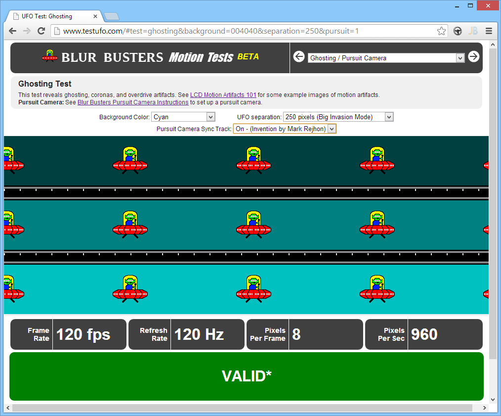
- TestUFO: Ghosting Test
www.testufo.com/ghosting
This is good for closer analysis of ghosting and overdrive effects. Mark Rejhon also invented a low-budget pursuit camera technique which can be used with this test for inexpensive scientific analysis. Adjusting for longer strobe length will increase motion blur, making the UFO alien eyes and white dots harder to see. - TestUFO: Blur Trail Test
www.testufo.com/blurtrail
Use custom configurations of this same test using a thick bar and complementary colors (e.g. try dark yellow/pale blue) in browser full-screen mode. This can be very good for fine-tuning strobe timing, strobe phasing, and adjusting overdrive settings. There can be more/less ghosting at the top/bottom edges of the screen, where the ability to adjust strobe timing/phasing can improve. - TestUFO: Flicker
www.testufo.com/flicker
Used in conjunction with a high speed camera (becoming more common, thanks to cheap 480fps GoPros and 1000fps-capable smartphones), it can be useful for verifying the proper timing of a strobe backlight or scanning backlight. See this annotated diagram of a frame of high speed video. - TestUFO: Strobe Crosstalk
www.testufo.com/crosstalk
This is an excellent test for calibrating strobe crosstalk, e.g. strobe phase/length adjustments. It is currently used with some strobe utilities including Blur Busters Strobe Utility.
These are the main useful tests for strobe backlight improvements. There are also several other TestUFO tests, selectable at the top of www.testufo.com
Tip for Experimenters: Turn ON/OFF the blur reduction mode while viewing TestUFO Moving Photo. Also, TFTCentral also measured the strobe lengths of the various progammable LightBoost strobe modes. Observe the differences in motion blur in the windows of the castle at the top of the moving photo. Your eyes are actually witnessing the motion clarity difference of 1.4ms strobes versus 2.4ms strobes! (A mere 1 millisecond difference). It is roughly similiar to the difference between a medium-persistence CRT monitor and a longer-persistence CRT monitor.
New TestUFO motion tests are being developed; if you require a specific specialized TestUFO motion tests, contact [email protected] to send suggestions of additional motion tests and improvements that are needed.
Photographing Motion Blur: Stationary Camera vs Pursuit Camera
If you choose to do motion blur measurements using a camera, this section becomes important to more easily understand the correlation between various motion blur measurement methods, and human perceived motion blur.
For motion blur measurements, it is very important to observe the distinction between stationary camera versus pursuit camera. Stationary cameras/eyes behave differently from moving cameras/eyeballs that are tracking motion. It is possible to have motion blur even when pixel transitions are instantaneous, as demonstrated in the animation at www.testufo.com/eyetracking. The sample-and-hold effect is a common explanation, and is also explained in the article, Why Do Some OLEDs Have Motion Blur?
Stationary Camera: Capture of Pixel Transitions
A stationary camera is good for photographing pixel transitions statically. It accurately captures ghosting effects, as incomplete pixel transitions leaking into the next refresh cycle. However, it is not a complete representation of commonly perceived display motion blur and motion artifacts, because stationary camera excludes tracking-based motion blur.

Example: Stationary camera photo of a moving object on a display.
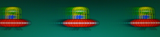
Pursuit Camera: Accurate Capture of LCD Motion Artifacts
Pursuit camera are used by display manufacturers for testing (e.g. MotionMaster, and other MPRT pursuit cameras, as well as doing a scientific paper search for “pursuit camera for displays” at Google Scholar, SID.org and other places). This is simply a camera that follows on-screen motion. These (usually) expensive cameras are extremely accurate at measuring motion blur and other artifacts, since they simulate the eye tracking motion of moving eyes.
Example: More accurate representative photo of human-perceived ghosting/motion blur on LCD.
Blur Busters has developed an inexpensive peer-reviewed pursuit camera method which operates in conjunction with the Blur Busters Ghosting Test (www.testufo.com), and also makes possible accurate photography of common LCD motion blur artifacts.
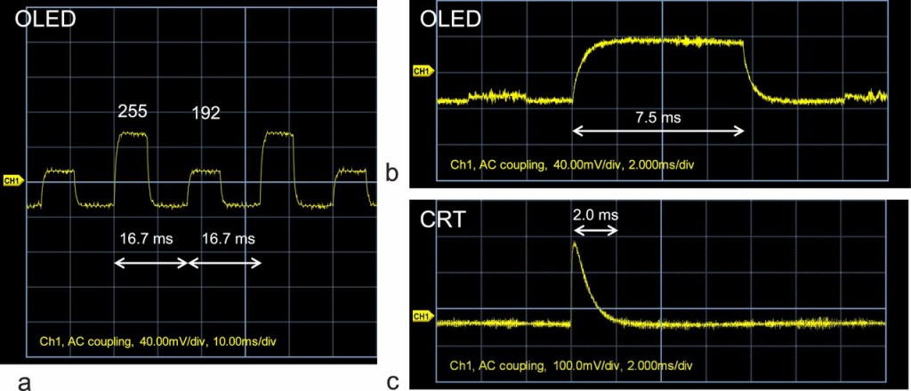
When most of a pixel transition is quicker than a refresh cycle, tracking-based motion blur becomes more dominant than ghosting-related motion blur (caused by slowness of transitions). It’s possible to have a situation where you have less ghosting but more motion blur, or vice-versa. OLEDs are very fast (e.g. perfectly completed OLED pixel transitions) but more motion blur (e.g. more tracking based motion blur, due to sample-and-hold/persistence), as seen in Why Do Some OLEDs Have Motion Blur?.
Presently, certain gaming monitors that utilize the better strobe backlights (e.g. NVIDIA LightBoost, EIZO Turbo240) have been found to have less motion blur than current 2013-model OLED HDTV’s. Despite the fact that OLEDs are faster at pixel transitions, the current OLEDs have higher persistence, caused by the longer sample-and-hold time (longer pixel visibility time). Several recent strobe-backlight LCDs released in late 2013, have less motion blur when viewing real-world motion such as video games, panning scenery, and moving photo tests. On these displays, transitions are sufficient fast enough to only create faint ghosting effects that is similar to very faint 3D crosstalk. Here, the ghosting becomes faint enough to disappear in the noise floor of the on-screen motion (e.g. much like faint 3D crosstalk becomes hard to find). In this situation, tracking-based motion clarity becomes the dominant factor on displays that finish at least most of pixel transitions before the next refresh cycle. This creates a situation where you may still have faint ghosting, but still far less overall perceived motion blur. This leads to situations where strobe-backlight video gaming LCD monitors, have less perceived motion blur during typical material than on current 2013-model OLED HDTVs. Typical material includes panning, turning, scrolling, strafing in video games, that leads to panning motion similar to TestUFO Moving Photo Test.
The confusion between transition-related ghosting effects, versus tracking-based motion blur, can lead to confusion in the industry where multiple reviewers (CNet, HDTVTest, BlurBusters, etc.) have published articles that describe OLED motion blur that disagree with findings by other reviewers (DisplayMate, etc).
This is due to the difference between stationary viewing (stationary camera/stationary eye) versus tracking motion (pursuit camera/tracking eyes). The former only measures transition-related ghosting, while the latter also captures tracking-based motion blur.
Also, video games involve closer viewing distances, wider FOV, faster panning motions, sharper graphics, little or no source-based motion blur. Games are much more demanding than television/movies, as detection of motion blur is much more sensitive in these situations. In fact, there are high-end gamers (game industry equivalents of videophiles) that immediately notice the motion clarity loss caused by a mere 1 millisecond of extra persistence.
For examples of pursuit camera photography done by Blur Busters, see:
– LCD Motion Artifacts 101
– LCD Overdrive Artifacts
– LightBoost 10% versus 50% versus 100%
Advanced Strobe-Optimized LCD Overdrive Algorithms
Modifying an existing fast 60Hz LCD (<= 2ms), to strobe its existing LED backlight, is simple for an experienced electronics hobbyist equipped with the necessary tools and knowledge, as shown above. Assuming you use a long enough blanking interval, a custom response time acceleration algorithm can be avoided, and a hobbyist can skip doing a custom response time acceleration.
However, manufacturers need to consider this, especially at higher refresh rates. Many artifacts start to appear due to more incomplete LCD pixel transitions between strobes, as you go higher in refresh rates. When refresh rates begin to enroach the pixel transition limitations of the LCD, the pixels at the bottom edge are far fresher than the pixels at the top edge, and thus begin to require different overdrive treatment to eliminate crosstalk (double-image effects) problems between refreshes.
The objective of response-time-acceleration algorithms optimized for strobe backlights (like the custom algorithm used for LightBoost) is to make sure the pixel is as close as possible to its accurate color value, at the exact moment of the strobe flash. Pixels transitions at the bottom edge of the screen will typically be fresher and less complete than pixels at the top edge of the screen, so experimentation of adding Y axis math to the response time acceleration is very desirable for high-refresh-rate strobe backlights.
Experimenting with high-refresh-rate strobing (e.g. 120Hz+ strobe back lights) ideally requires modification of the overdrive (response time acceleration). This is often beyond the scope of hobbyists, but if you are a small scale manufacturer (e.g. special game displays), it is worthwhile to know that it is possible to do software based prototyping of response time acceleration algorithms using shader programming on a GPU.
Software-based response time acceleration prototyping: Some versions of the AMD Radeon drivers have had a GPU-based LCD Overdrive feature built in. This shows the GPU can be used to calculate the response-time acceleration compensated pixel values. For example, when changing from a 25% to 50% grey, the pixel value in the next refresh might need to be a 60% gray to quicken the transition from 25% gray to 50% gray. To help speed transitions to blacks and to whites, you need overshoot room. So one will want blacks that is slightly higher than full-black, and whites slightly lower than full-whites, to give extra headroom for response time acceleration.
The whole screen becomes one big matrix math array (separately for each R, G, and B) that’s run on the GPU in real time, to create compensated color values. Monitor manufacturers often use test patterns and measuring equipment to determine the optimal response time acceleration data to be built into the monitors. Things like temperature and panel differences can also affect LCD pixel transitions, so some of this is done on a best-effort basis, or even the addition of temperature sensor data into response time acceleration calculations.
That said, prototyping an algorithm on a GPU can be a good source of experimentation before creating firmware that gets permanently installed on a computer monitor. A big advantage of software-based response-time-acceleration is it can be used on any LCD panel (with its hardware response time acceleration disabled), so this makes a good manufacturer prototyping platform for response time acceleration algorithms, before being ported to LCD controller firmware.
Bear in mind that GPU buffering for response time acceleration can add input lag (especially during software-based prototyping), especially if you also use lookforward (overdrive calculations based on next refresh). So for minimum input lag, you want to stick to lookbehind-only response time acceleration to minimize input lag, and stick to algorithms that can be done in a real-time scanout in monitor firmware. LightBoost displays use only lookbehind during response time acceleration.
If you are experimenting with high refresh rate LCD’s (e.g. 240Hz), you may need to factor in more than one previous refresh in the calculations for response-time acceleration algorithm (e.g. a two or three refresh history) for best results.
High-quality shutter-glasses 3D panels already have built-in custom response time acceleration out of necessity, so verify that a wheel is not being reinvented before embarking in the difficult art of programming custom response time acceleration for an LCD panel.
Another need is to eliminate banding when using Y-axis compensated overdrive algorithms. Banding easily appears during LightBoost mode in the full-screen TestUFO Flicker Test, which shows math rounding errors in Y-axis compensated RTC. Improved strobe modes needs more precision (more bits of LUT’s, floating-point values instead of integers, etc), to eliminate these banding issues that can occur. (Presumably, G-SYNC’s optional strobe mode, has probably worked to reduce these banding issues).
One newly discovered interaction with strobe backlights is that strobe backlights can amplify visual artifacts caused by an LCD panel’s voltage inversion (alternating positive and negative voltages used in order to prevent image retention on LCD’s). Some 120Hz panels exhibit distortions when viewing TestUFO: Moving Inversion Pattern. Some panels may use modified voltage inversion schemes that have less interactions with strobe backlight operation.
For manufacturers that are reading this: If strobe-optimized overdrive algorithms are too complex, consider including strobing anyway at lower refresh rates. There are people (including myself) who prefer playing games on a CRT 85fps@85Hz, because it still has less motion blur than LCD 120fps@120Hz.
Advanced Input Lag Considerations
Strobe backlights can create some minor input lag because you are waiting for the whole LCD panel to finish refreshing before strobing the backlight. This can be an issue for some high-end competitive gamers. However, for many people, the faster human reaction time from reduced motion blur outweighs the minor added input lag, especially at higher refresh rates (120Hz). That said, one should always strive to reduce input lag to the fullest extent possible. In addition, strobe backlight modes can simply be configured/disabled via monitor menus or graphics drivers, for those input-lag-critical situations or personal preference.
Monitor manufacturers (monitor firmware engineers) have to work to minimize input lag as much as possible during strobe backlight operation, using techniques such as:
- If possible, don’t fully buffer refreshes. Do partial buffering of refreshes.
If you are using an accelerated-refresh approach to create larger intervals between refreshes for strobing (e.g. refreshing invidual 1/120sec refreshes in just 1/240sec), then begin refreshing the LCD after buffering part of the refresh from computer signal (e.g. half of a refresh). Basically, the raster data from the video input (DVI/DisplayPort/HDMI) is put into a FIFO buffer within the monitor. That way, an accelerated panel refresh is finished at the exact moment the final pixels (bottom edge of screen) arrives into the monitor’s input. - Do all processing and overdrive in real time, “on the fly”, where possible.
Operations that does picture adjustments and/or overdrive algorithms (response time acceleration) should be done in real time, on the fly where possible. Framebuffering should be avoided where unnecessary, and all processing done in real time while refreshing the panel. - Use ultra high refresh rates, if full framebuffering becomes needed.
In situations where framebuffering is unavoidable (e.g. multipass refresh algorithms, advanced IPS/VA overdrive algorithms), try to for faster frame transmission times. This can be achieved by the use of an ultra high refresh rate such as 240Hz native from the computer, or even 120Hz with black frames, or the use of ultra large trailing blanking intervals (e.g. huge vertical back porch). This allows faster transmission of individual visible refreshes. This reduces input lag caused by the frame transmission time, for situations where framebuffering is required. High speed cables such as as DisplayPort 2.0 and HDMI 2.0, theoretically permits the use of 1920×1080 running at 240Hz (and potentially greater), providing better opportunities to reduce input lag in fully-framebuffered situations.
Advanced Multipass Refresh Algorithms
One method of cleaning up LCD refreshes to make them strobe-friendly, is a multipass refresh. For example, refreshing the LCD panel two times on the same image (one refresh from computer converted into two duplicate panel refreshes), before strobe-flashing during the clean period at the end of the second-pass refresh. The first refresh pass can be a very heavily-overdriven refresh pass done in total darkness, and the second refresh pass can be a clean-up refresh pass to stabilize the LCD pixels (eliminate overdrive artifacts), before strobing the backlight after the refresh is cleaned-up of overdrive artifacts.
This is a useful technique to speed up pixel transitions on slower LCD panels such as IPS LCD’s and VA LCD’s, while fixing overdrive artifacts. The multipass refresh technique is being done on certain LCD’s. For example, an IPS or VA LCD can be refreshed at 240Hz (duplicate refreshes: one overdriven refresh pass and one non-overdriven refresh pass), for cleaner refreshes during 120Hz strobe flashes.
Another potential advantage of a multipass refresh is that LCD inversion artifacts can be engineered to become less visible during a single refresh (for those particular panels that use voltage inversion during every other refresh).
In addition, at the lower end, this can also be experimented with a modification of TN 120Hz and 144Hz LCD monitors (and on overclocked IPS 2560x1440p monitors) and strobing its built-in backlight at half the refresh rate (such as 60Hz or 72Hz). Although custom strobe-optimized response time acceleration algorithms would be ideal, a multipass refresh may simplify strobe backlights for homebrew situations (e.g. eliminate the need for custom overdrive algorithms at lower refresh rates, eliminate the need to use a large blanking interval). This may be one possible technique of achieving modded 60Hz or 72Hz LightBoost with potentially better color quality. For example, electronically suppressing the existing LightBoost strobe voltage for every other refresh, then duplicating the 60Hz (or 72Hz) refreshes to fit a 120Hz (or 144Hz) refresh rate, and making sure the strobe occurs only right near the end of the second-pass of the refresh. This way, two passes of a refresh occurs, which usually leads to even cleaner refreshes. GPU power requirements would be lower, requiring only 60fps (or 72fps) for the perfectly-sharp CRT-like motion clarity, while avoiding objectionable overdrive artifacts. There would still be lots of flicker, however, at these lower strobe rates, similar to a 60Hz or 72Hz CRT. A higher refresh/ rate/strobe rate is preferred where possible.
Flicker/Eye Comfort Considerations
Some monitor manufacturers have an initiative to completely eliminate flicker from computer monitors. This includes elimination of PWM (pulse-width modulation) for backlight dimming, and instead using DC voltage modulation for dimming the backlight. This is excellent, and monitors should always provide a flicker-free non-strobe mode.
However, it’s worth noting that sometimes strobing (to eliminate motion blur) actually reduces eyestrain in many situations, for people who are motion-blur sensitive (people who get eyestrain from motion blur).
Although flicker can create eyestrain into itself, another cause of eyestrain during PWM is the appearance of ugly PWM motion artifacts:
Appearance of www.testufo.com/ghosting using PWM dimming at lower Brightness settings.
For certain people, this is a bigger cause of PWM eyestrain than the PWM flicker itself! (e.g. people who never eyestrain with CRT but now get eyestrain with PWM even in situations where excessive blue light from common white LED’s is eliminated).
It is also noteworthy that there is also a market for 240Hz-native-refresh displays, for people who dislike flicker of all forms and prefer a 240Hz flicker-free display. A 240Hz native refresh rate (flicker free, no strobing) which would have the equivalent motion blur of a strobe-backlight display utilizing approximately 4ms strobe flashes. This is a useful consideration for a theoretical 240Hz LCD gaming monitor. Higher refresh rates require extremely powerful GPU’s, though 240fps is easily achieved on modern GPU’s in older games (e.g. Source Engine games such as Counterstrike and Team Fortress 2) for an excellent technical demonstration of the incredible flicker-free motion fluidity that 240fps@240Hz would give. And if a strobing feature can be added, 240Hz strobed would have far less flicker than either 60Hz or 120Hz strobed.
As a rule of thumb, there should ideally be an easy ON/OFF setting for the motion blur reduction backlight.
- When strobe backlight is OFF, use PWM-free backlight dimming.
This reduces eyestrain for flicker-sensitive people. Ideally, the brightness dimming range should be wide enough so that the monitor can be dimmer than an iPhone at minimum brightness setting. Many people like bright monitors, but many other people have found some modern gaming monitors too bright even at Brightness “0” setting. - When strobe backlight is ON, use only one strobe flash per refresh.
This reduces eyestrain for motion-blur-sensitive people. In addition, the use of a high strobe rate (120Hz or greater) to eliminate visible flicker, similiar to using a high-refresh-rate CRT monitor, to further reduce the odds of eyestrain.
Reducing Research & Development Costs For Manufacturers
During 2013, several display manufacturers began to contact Blur Busters asking to add/improve/beta test a strobe backlight to their monitors (contact info for free help). Here is simple, generic advice for the most inexpensive methods of adding a strobe backlight to a new computer monitor model, depending on the design of the existing LCD panel that you choose to implement in the design of a new computer monitor.
Owners (CEO’s) of manufacturers may not understand this engineering information. Also, many outsourced manufacturers (e.g. factories in China) may not understand motion blur reduction via strobing either. However, there are ways to simplify research & development by separating the hardware manufacturing requirements from the firmware requirements. You can then keep things simple for an outsourced factory, while shifting most of the complexity to a firmware programmer located somewhere else (e.g. in your office, or in your country).
Requirements for Factory / Outsourcing / Electronics
The minimum possible consideration for the factory (and without needing the factory to understand motion blur reduction strobing fully) is that the display firmware simply needs to be able to turn ON/OFF the edgelight/backlight rapidly and precisely, and the firmware needs to know exactly when each refresh occurs. The rest of the details can then later be handled by a software programmer creating a custom monitor firmware.
Good integration between hardware and firmware improves things (e.g. Y-axis compensated response time acceleration) but this is actually no longer critical to producing a useful motion blur reduction strobe backlight. This is because several existing raw 120Hz LCD panel assemblies are now fast enough to be strobed, using existing edgelights, without any panel modifications.
It is wholly possible that your LCD panel already supports this. Carefully study the specifications of your LCD panel, to decide whether or not further custom circuit modifications are necessary or not, and talk to your engineers. There are additional considerations that enhance a strobe backlight monitor, however, these are reasonable minimum hardware requirements:
- Electronics Circuit Requirement #1: Firmware access to refresh timing
Firmware needs access to knowing when the LCD refresh begins. This is important so that it’s possible to have somebody else design firmware that flashes the backlight in perfect synchronization to each refresh, e.g. 120 times per second at 120Hz.
To the electronics circuit designer: this should be accessible as an interrupt (e.g. interrupt on a GPIO line connected to vertical synchronization signal). However, it could be a polled chip register (still usable). The timing should be as accurate as possible, to minimize side effects. The refresh signalling should not randomly vary from refresh-to-refresh by more than a few microseconds, where possible. - Electronics Circuit Requirement #2: Instant firmware control of backlight
Firmware needs to be able to turn ON/OFF the LED edgelight/backlight instantly, rapidly, and accurately. This is similar to hardware-based PWM for brightness dimming (and does not exclude continuing to use the hardware), except that the firmware is controlling the exact timings of the ON/OFF cycles instead. This could be accomplished either as a separate ON signal and OFF signal, or as a single signal that does a programmable-length backlight flash (of an exact microsecond length).
To the electronics circuit designer: Blur Busters confirms microseconds matter critically! If microseconds are impossible, do your best (e.g. under 5 microseconds). Strobe length accuracy is vastly more important than strobe timing accuracy. A strobe length variance of 1% means a 1% variance in human perceived brightness. 1/100th of 1ms equals 10 microseconds! It actually created human-visible undesirable candle-flame-style flickering, a bug discovered in a beta strobe-backlight monitor sent to Blur Busters from an undisclosed major manufacturer.
Manufacturers looking to reduce costs of adding a strobe backlight, should takes advantage of crowd-sourced intelligence. This can take a lot of work off a manufacturer of a display, for strobe backlights. The tinkerer community (e.g. LightBoost users, monitor overclocking users, ToastyX patching utilities, etc) is capable of creating software and playing with software utilities that optimize their display, including custom video timings & resolutions, custom calibration of the display, including new strobe calibration software, etc.
Requirements for Monitor Firmware Programmer
First, make sure you got your circuit boards supporting strobing in the minimum possible way (see above). That’s important first. A monitor manufacturer running on a tight budget, could also theoretically do the custom firmware later (or hire an outside enthusiast programmer from the Blur Busters gaming community, contact info).
These simplified requirements below allows quicker and simpler firmware modifications, to support quality strobing. These requirements shifts most of the complexity of adjustment/calibration fine-tuning to the end-user, or during later-stage in-house experimentation (e.g. in-house utilities), or third party utilities including utilities designed and created by Blur Busters (contact info). While this may not be as good as an engineering effort by a major manufacturers that very closely integrates the hardware and firmware, having simple rudimentary strobing actually actually already greatly improves the performance of many existing ‘fast’ LCD panels, utilizing its existing edgelight, and with little hardware modification (and potentially none).
- Include strobe adjustments, via on-screen menu and/or DDC command.
As explained earlier (see high-speed videos), pixel transitions for the whole LCD ideally needs to be mostly finished before the strobe is flashed. Slower LCD technologies (IPS and VA) will need more time between refreshes, so this an important step.- Strobe enable/disable.
This switches between motion blur reduction strobing (low-frequency PWM), versus regular steady backlight (PWM-free or high-frequency PWM) .
– Users who never use strobing (e.g. people who really hate CRT flicker).
– Users who prefer to strobing 24/7 (e.g. CRT lovers and motion blur haters).
– Users who turn off strobing during during desktop or web browsing, while enabling motion blur eliminating strobing during playing games. - Strobe length adjustment during strobe mode.
This is the amount of time the backlight/edgelight is turned ON during a refresh.
There is a trade-off involved. This allows end-users to choose their preference.
– A longer strobe is brighter but has more motion blur (higher persistence).
– A shorter strobe is dimmer but has less motion blur (lower persistence).
– Extremely long strobe lengths can also create more ghosting effects (Visibility of different LCD refreshes leaking between refreshes, during strobing).
A great test that demonstrates the blur-brightness tradeoff is testufo.com/photo. This is seen on a LightBoost monitor, especially at higher panning speeds, while adjusting the LightBoost strobe length. Ideally, you want to allow very short strobe lengths (0.5 milliseconds) as well as very long strobe lengths (more than 2 milliseconds, possibly adjustable to more than 4 milliseconds). Blur Busters testing have actually shown that several humans actually see benefits of using strobe shorter than 1 milliseconds. - Strobe timing (phase) adjustment during strobe mode.
This is the exact timing of the strobe flash, relative to the timing of the refresh (vertical synchronization interval). Strobe can be made to occur early or later.
Incorrect timing of the strobe flash (e.g. middle of a refresh) can cause a “blurry-tearing” effect during fast horizontal panning motion. Easy user calibration of strobe length can also be done at testufo.com/blurtrail when running full screen (Height->”Full Screen”). The user can then easily adjust the strobe timing adjustment until the “blurry tearline” goes offscreen, and the center horizontal band of the screen has minimum ghosting. There may still be minor ghosting at the top/bottom edges of screen (especially if the panel is very fast), this becomes much improved if there’s more time between refreshes for pixel transitions to complete (see below).
- Strobe enable/disable.
- If possible, find an easy way to insert bigger pauses between LCD refreshes.
As explained earlier (see high-speed videos), pixel transitions for the whole LCD ideally needs to be mostly finished before the strobe is flashed. Slower LCD technologies (IPS and VA) will need more time between refreshes, so this an important step.- Make display to accept a large blanking interval from the input.
This shifts this responsibility to the GPU. Users of Custom Resolution Utilities (e.g. ToastyX, PowerStrip, NVIDIA, etc) can simply manually adjust the video timings to create a large blanking interval that lasts several milliseconds (e.g. a 1080p signal with a 500-pixel blanking interval, such as a bigger “Sync” or bigger “Front Porch”). Make sure that by doing this, actually accelerates the LCD scanout (e.g. refreshing a 85Hz refresh in 1/120sec, followed by idling until the next refresh) - Or, if display design uses frame buffering, use a faster LCD scan-out.
Framebuffering is known to adds input lag. However, it present an opportunity to do an LCD scanout at a speed faster than the refresh rate normally warrants. For example, if you’re running at 75Hz, the LCD driver could scan-out the refresh in 1/120sec instead. This creates extra time between LCD refreshes for strobing. - Or, if display design allows higher resolution input than panel, try using dummy extra vertical resolution as a delay between refreshes.
For example, an LCD controller that can accept 1920×1440 signal for a 1920×1080 panel. Program the LCD controller to only display the topmost 1920×1080 (of a 1920×1440 signal). The bottom part of the signal is simply a time delay to create extra time between refreshes for strobing. End users can simply create a special custom timing mode (e.g. ToastyX Custom Resolution Utility) to force Windows to use only the topmost 1920×1080 pixels of the 1920×1440 signal. This is easily achieved by the use of an unusually large “Front Porch” value in signal timings. - If this is impossible, try your best.
Work with your LCD panel’s existing limitations to the best of your ability. Find ways to add a few tens of microseconds to the interval between refreshes. Find ways to add an extra few hundred milliseconds to your blanking interval.
– Are there registers in your LCD controller that allows bigger blanking intervals?
– Are there registers in your LCD controller that allows higher-vertical-resolution signal that’s taller than your LCD panel?
– Are there registers in your LCD controller that allows you to do a faster scan-out of a buffered refresh?
– Are there registers in your LCD controller that allows cropping of the input signal (e.g. displaying only the topmost part of a signal)? - Even if you can’t do any of the above, don’t give up. The end-user ability to control strobe length/timing can somewhat reduce flaws caused by inability to create a large blanking interval between refreshes. This is not ideal, but often still leads to useful strobing at lower refresh rates.
- Make display to accept a large blanking interval from the input.
Ideally, strobing should be refresh-rate adaptive. Ideally, the strobe backlight operate at any refresh rate, even all the way down to 60Hz (for emulator and console use), while allowing strobing at higher refresh rates (to reduce flicker). Third parties can thus create utilities and software that easily calibrate a strobe-backlight monitor, possibly manufactured by a factory that never knew about motion blur reduction strobing, as long as the LCD panel is generally sufficiently fast enough to allow the software implementation of the capability (given the minimum hardware requirements of allowing firmware to precisely control/modulate the LED edgelight/backlight).
Further advanced enhancements are optional (e.g. DDC commands to customize response-time acceleration, to allow third party software to create custom lookup tables for the monitor). Such advanced extras can be included and publicized to allow crowd sourced calibration/improvements of your computer monitor. As seen by LightBoost enthusiasts (just google “LightBoost”) and the existence of ToastyX Strobelight, the high-end monitor community is full of fans, geeks, programmers, designers that are interested in this type of tweaking.
Alternative Display Technologies (OLED, etc)
Some new display technologies such as OLED are prone to the motion blur problem (see Why Do Some OLED’s Have Motion Blur?).
(Credit: “Evaluation of an organic light-emitting diode display for precise visual stimulation“)
OLED persistence was shown by scientists and testers (e.g. HDGuru, japanese scientists, etc) to fall greatly short of mainstream expectations, at least on large-screen format OLED displays. Tests at HDGuru found that OLED motion blur can be as bad as a 60Hz LCD.
Fortunately, there are some solutions to reducing OLED motion blur. One is using passive-matrix OLED’s (brightness problem at large screen sizes, though can be partially compensated by illuminating whole row of pixels at a time). Another is to use a rolling-scan on active-matrix OLED’s, where rows of OLED pixels are illuminated, while simultaneously turning off OLED pixels off a few pixel rows behind (Sony Trimaster PVM-2541 OLED does this, albiet with 7.5ms of OLED persistence). For ultra-low persistence OLED’s, a rolling scan of about 1ms could be achieved, to produce ultra-low motion blur (useful for virtual reality applications as well).
Strobing on Variable Refresh Rate Displays
New section added October 19th, 2013
With nVidia’s G-SYNC announcement, variable refresh rate displays are now a reality today. Refresh rates can now dynamically vary with frame rates, and it is highly likely that nVidia has several patents on this already. If you are a monitor manufacturer, contact nVidia to license this technology, as they deserve kudos for this step towards tomorrow’s perfect Holodeck display. That said, many users are now clamoring to use LightBoost due to media coverage, and would like to keep low-persistence simultaneously with G-SYNC. There are technical challenges and side effects that must be solved when using a variable refresh rate with a strobe backlight.
An idea that Mark Rejhon of Blur Busters has come up with is a new creative PWM-free-to-strobing dynamic backlight curve manipulation algorithm, that allows variable-rate backlight strobing (LightBoost), without creating flicker at lower frame rates.
It is obvious to a scientist/engineer/vision researcher that to maintain constant perceived brightness during variable-rate strobing, you must keep strobing duty cycle percentages constant when varying the strobe rate. For motion blur elimination, you are limited to one strobe per refresh. This requires careful and precise strobe-length control during variable refresh rate, as the display now refreshes dynamically on demand rather than at discrete scheduled intervals. However, a problem occurs at lower framerates: Strobing will cause uncomfortable flicker at lower refresh rates.
Mark Rejhon has invented a solution: Dynamic shaping of the strobe curve from PWM-free mode at low framerates, all the way to square-wave strobing at high framerates. The monitor backlight runs in PWM-free mode during low refresh rates (e.g. 30fps@30Hz, 45fps@45Hz), and gradually become soft gaussian/sinewave undulations in backlight brightness (bright-dim-bright-dim) at 60fps@60Hz, with the curves becoming sharper (fullbright-off-fullbright-off) as you head higher in framerates, towards 120fps@120Hz. At the monitor’s maximum framerate, the strobing more resembles a square wave with large totally-black-gaps between strobes.
Example:
10fps@10Hz — PWM-free backlight
30fps@30Hz — PWM-free backlight
45fps@45Hz — PWM-free backlight
60fps@60fps — Minor backlight brightness undulations (bright / dim / bright / dim)
80fps@80Hz — Sharper backlight brightness undulations (very bright / very dim)
100fps@100Hz — Starts to resemble rounded-square-wave (fullbright / fulloff)
120fps@120Hz and up — Nearly square-wave strobing like original LightBoost
This would be a dynamically variable continuum all the way in bewteen too, much like automobile CVT instead of discrete gears in automobile transmissions. You avoid flicker at lower frame rates, and you get full strobing benefits at higher frame rates.
Simpler algorithm variations are also possible (e.g. keeping a square wave, and using only pulsewidth / pulseheight manipulation to achieve the blending effect, but without curve-softening). This is included as part of this general idea of blending from PWM-free at lower refresh rates, to strobing at higher refresh rates. The trigger framerates may be different from the examples (or may even be adjustable via a user flicker-threshold setting), but the concept is the same.

Napkin Sketch: Strobing Digram
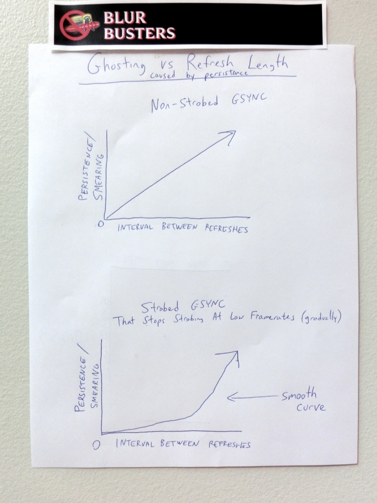
Napkin Sketch: Persistence Curve
It is essential to maintain average light output of the brightness on a rolling-average basis at all times, and that the frequency of the light changes is sufficiently high (>60Hz) to avoid human detection of flicker. Different people will have different flicker detection thresholds, so a reasonably high-percentile needs to be achieved (e.g. aiming for >90% of people not seeing side effects from the variable-rate strobing).
A display engineer would quickly ask about minimize input lag during variable-rate strobing (which would be an optional setting). An engineer may ask; should we know when the future frame arrives before calculating strobe length (making frame buffering necessary; creating input lag)?
Strobe curve shaping calculations (strobe width/length) can simply be based on time since previous refresh. It is not necessary to do frame lookahead (which would create input lag due to frame buffering). Although that means the strobe length is computed based on a previous refresh, it apparently doesn’t matter which frame the calculated strobe lengths should go, if using: (1) one strobe/peak per refresh; (2) proper timing of start of strobe; (3) constant average light output is still maintained. This may allow adaptive-rate strobing with no additional latency. No human side effects would seem to be noticeable by using trailing frame history to compute strobe curves, as long as these conditions are met. Technically, it would simply cause persistence to lag by a single frame (e.g. during a sudden frame rate speedup, the resulting further motion blur reduction would lag by 1 frame) which would not be noticeable. And, most of the time, frame rate fluctuations are gradual so this turns into a moot issue, if challenges (1), (2), (3) in this paragraph are solved.
It is also possible that overdrive overshoots will gradually become more and more visible, as the strobing transitions to steady state (PWM-free) during a slowly falling framerate scenario. This is a side effect that needs to be considered, as overdrive algorithms for strobe backlight use, can be different from overdrive algorithms used in PWM-free mode, considering the use of Y-Axis Compensated Overdrive algorithms being used.
Alternative to PWM-free: For display electronics incapable of being PWM-free, the use of high-frequency PWM can be used as a substitute to PWM-free. For display electronics incapable of changing pulse height, the use of high-frequency PWM can be used to create the intensity levels within the brighter-darker intensity changes at the intermediate refresh rates (bright-dark-bright-dark modulations versus fullbright-off-fullbright-off). Brightness curves can even be created by dynamically changing PWM. Care must be taken to ensure that PWM-rate transitions doesn’t create flicker. Care must be taken that trailing average brightness remains as constant as possible (at timescales that approach human flicker-detection thresholds) at all times, including any overlapping high-frequency and low-frequency components of PWM. Care must be taken to ensure that there is no noticeable side effects to white LED phosphor behavior, during on-the-fly strobe frequency changes.
Note: This idea is FREE but if any party or monitor manufacturer uses this idea (if no patent application dated before October 19, 2013 covers this invention of variable-rate strobing), please give Mark Rejhon / Blur Busters appropriate due credit. It is realized NVIDIA has several patents, however, none appears to be covering this (As far as I know) additional improvement being suggested: Combining strobing and variable refresh rates, while simultaneously avoiding flicker at lower refresh rates. As of this writing, research is being done on any prior art, to determine whether anyone dynamically considered blending from PWM-free to square-wave strobing. If anyone else already came up with this idea, or already documented in a patent application prior to October 19, 2013, please let me know & due credit will be given here.
2013 ADDED NOTE: This idea/research is being offered to any party for FOR FREE – Credit is only asked for (Name Mark Rejhon & website Blur Busters) for this idea, in someplace permanent, such as the references section of a subsequent patent application, or Credits section of a monitor manual, etc.
2017 ADDED NOTE: See update at Blur Busters GSYNC+ULMB post.
Linear Motion Blur Versus Gaussian Motion Blur
As an interesting aside in scientific curiosity, it is worth noting that strobe curves apparently affects the shape of the resulting display motion blur, for strobe lengths that are still long enough to create noticeable motion blur. Square-wave strobes creates linear display motion blur, while sine/gaussian-wave strobes creates gaussian display motion blur. This will be clearly noticed in certain motion tests such as www.testufo.com/blurtrail during strobe curve manipulation experiments. However, the shape of the strobe curve will generally not matter in real-world gaming during short strobe lengths (square-wave strobing versus gaussian-wave strobing).
A lot of motion blur is already eliminated during backlight strobing, especially during short strobes, that the shape of motion blur of a strobe-backlight display is typically not noticeable at these levels. What’s more important is successfully achieving high quality strobing. On the other hand, gradual strobe curves may simulate gradual CRT phosphor decay. Softer strobe curves may potentially reduce eyestrain, at the cost of adding back a slight amount of motion blur.
In motion tests on a LightBoost monitor (with LightBoost activated), when using the monitor OSD menu to quickly alternate between LightBoost=0% (use monitor OSD, set LightBoost to one setting below 10%, which uses a longer but dimmer strobe) and LightBoost=10% (shorter but brighter strobe) while viewing motion tests at TestUFO. (NOTE: TFTCentral has oscilloscope graphs of the shapes of LightBoost strobe curves) You only see subpixel-changes modulations in motion blur (less than 1 millimeter change in motion blur trail, during 960 pixels/second motion). It is observed that dynamic changes to the strobe shape (as long as the strobe is small) doesn’t create very noticeable or objectionable visual effects. This is a useful observation to be familiar with, when making adaptive-rate strobe backlights possible on variable-refresh-rate monitors (e.g. G-SYNC) while avoiding side effects. For that use case, avoiding visible flicker is more important.
Modern non-strobed LCD panels create tracking-based motion blur more similar to linear motion blur instead of gaussian motion blur. This is because pixel transitions are now much shorter than the refresh length. An excellent animation of this modern LCD behavior is the TestUFO Checkerboard Illusion (view this on a recent 1ms or 2ms LCD, preferably manufactured after 2010, with very good response time acceleration). This animation perfectly demonstrates modern LCD pixel GtG transitions more resemble a square wave rather than a gradual curve. This creates the checkerboard pattern in the optical illusion. This is not surprising, since modern LCD’s have majority (GtG 10%->90%) transition times of 1ms-2ms, a tiny fraction of a 60Hz refresh (16.7ms) and even 120Hz refresh (8.3ms), so GtG transition curves now mostly resemble square waves as GtG curves become de-facto cliffs to the human eye, and pixel ripples (overdrive) clears out more quickly, earlier during a refresh.
References
Advanced Strobe Crosstalk FAQ
Schematics for Overriding a LightBoost Strobe
European Researcher Marc Repnow’s LightBoost Site
ToastyX Strobelight; Enable LightBoost independently of nVidia Drivers
TestUFO: Blur Busters Motion Tests
For further discussions, or custom TestUFO motion tests, or contact [email protected]. In addition, if your project has benefited from the information on this page, please let us know!